
Industrial construction projects rely on strict, standardized rules for how power and control cables are routed, supported, and protected. In Vietnam, these rules are codified in the National Standard TCVN 9208:2012, which governs the design and installation of electrical cable systems in industrial and civil works. This article summarizes the standard’s scope, key terminology, and its most important practical requirements for engineers, contractors, and facility owners working with cable trays, cable ladders, wire mesh trays, conduit, and direct-buried cable.
Scope
TCVN 9208:2012 applies to the design and construction of cable routing systems that carry power and control cables with voltages up to 35 kV inside industrial plants, civil buildings, and similar works. It covers cable trenches, cable tunnels and galleries, cable trays and ladders, wire mesh cable trays, trunking, conduit systems, direct burial in the ground, and the boxes, joints, and glands used to connect and protect cables along these routes.
Key Terms and Definitions
- Cable trench: An underground structure, typically covered with removable slabs, used to route cables below grade while allowing access for installation and maintenance.
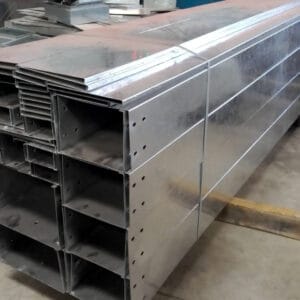
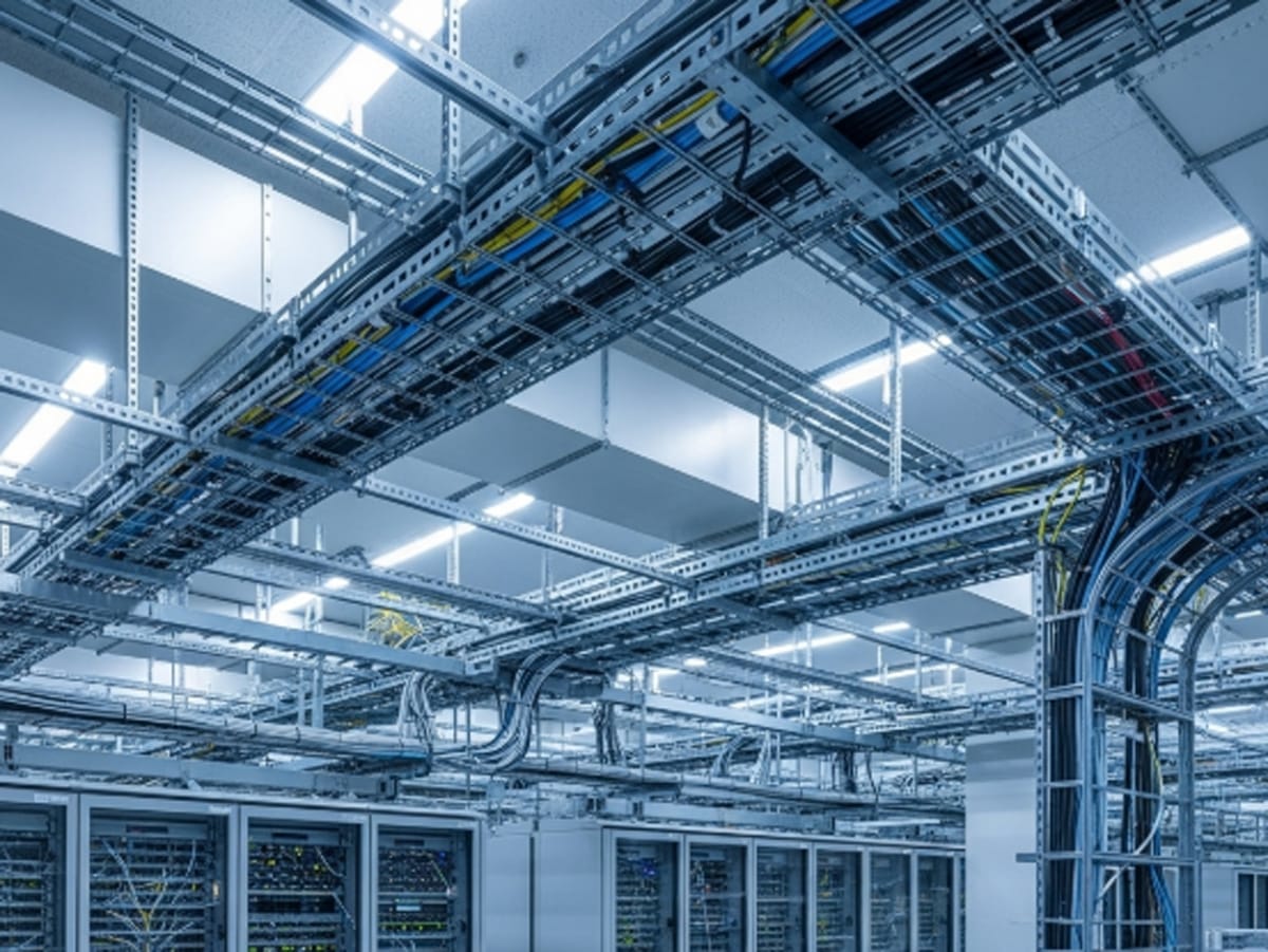
- Cable tray: A rigid, open or ventilated structure used to support and route power and control cables along a defined path.
- Cable ladder: A tray-type support system with widely spaced rungs, used mainly for heavier power cables that need strong mechanical support and good ventilation.
- Trunking (cable duct): An enclosed, often rectangular channel with a removable cover, used to protect cables while keeping them concealed and organized.
- Conduit: A tube (metal or plastic) through which one or more cables are pulled, providing mechanical protection, especially where cables cross walls, floors, or roads.
- Wire mesh cable tray: A tray made from welded steel wire, offering good ventilation, light weight, and flexibility for cable routing in light to medium-duty applications.
- Technical gallery (cable tunnel): A walkable underground or semi-underground passage built specifically to house cable routes and allow personnel access.
- Technical floor: A dedicated level or space within a building reserved for electrical and mechanical services, including cable routing.
- Technical shaft: A vertical duct or riser running through multiple floors of a building, used to route cables and other services between levels.
- Cable pit: A below-grade chamber, typically at a junction or turning point, used for cable pulling, splicing, or direction changes.
- Catch basin (drainage pit): A collection point built into a cable trench or duct system to gather and remove water, keeping the cable route dry.
- Duct bank: A group of conduits, usually embedded in concrete, installed together underground to route multiple cables along the same path.
- Cable joint box: An enclosure used to house a splice or termination between two cable sections.
- Cable gland: A fitting used to seal and mechanically secure a cable where it enters an enclosure, box, or piece of equipment.
- Low-voltage cable: Cable rated for systems up to 1 kV.
- Power cable: A cable designed to carry electrical energy to loads or equipment, as distinct from control or signal cables.
- Medium-voltage cable: Cable rated above 1 kV and up to 35 kV under this standard.
Key Requirements Summarized from the Standard
General Provisions
Cable routing systems must be designed so that cables can be installed, inspected, and replaced without damaging the cable insulation or the supporting structure. Different voltage classes and types of cable (power, control, signal) should be segregated or adequately separated to avoid interference and to simplify future maintenance. All supporting structures — trays, ladders, trunking, and conduit — must be sized with spare capacity for future cables, and must be properly earthed (grounded) where required.
Bending Radius
Every cable must be installed with a bending radius no smaller than the minimum specified by the cable manufacturer, and in general no smaller than the multiples of overall cable diameter set out in the standard for each cable type and construction (e.g., armored vs. unarmored, single-core vs. multi-core). Bends at tray/ladder turns, into cable boxes, and at conduit entries must be checked against this minimum to avoid stressing or damaging the insulation and conductors.
Cable Fill and Labeling
Trays, ladders, trunking, and conduit must not be filled beyond the maximum fill ratio set out in the standard, so that heat generated by the cables can dissipate properly and so that individual cables can be added or removed later. Cables should be arranged neatly, in a single layer where practical for power cables on trays/ladders, and bundled and labeled at regular intervals and at both ends so that each circuit can be identified without tracing its full length.
Fire and Penetration Sealing
Where cable routes pass through fire-rated walls, floors, or partitions, the penetration must be sealed with a fire-stopping material rated to restore the fire resistance of the structure. In areas with a higher fire risk or where cables run in bundles over long distances, fire-retardant or fire-resistant cable types and fire-stop barriers at intervals along trays and shafts should be used, consistent with the building’s fire protection design.
Installing Cable in Trays and Ladders
Trays and ladders must be securely supported at intervals short enough to prevent sagging under the full weight of installed cables, with additional support at turns, junctions, and vertical risers. Cables should be secured to the tray/ladder with ties or cleats at defined intervals, especially on vertical runs and at bends, without over-tightening in a way that deforms the cable jacket. Where trays or ladders cross expansion joints of a building, an expansion fitting or slack loop should be provided.
Installing Cable in Cable Boxes (Trunking)
Cable boxes and trunking must have removable covers for access, be sized to respect the maximum fill ratio, and provide smooth, rounded entry and exit points so cables are not cut or abraded by sharp edges. Joints and splices inside trunking should be made in a joint box or accessible section rather than concealed inside a closed run, and trunking crossing between fire compartments must be fitted with fire barriers as noted above.
Installing Cable in Conduit Systems
Conduit runs should be kept as straight as possible, with pull boxes or junction boxes provided at intervals and at multiple bends so that cables can be pulled through without exceeding the allowable pulling tension or bending radius. Conduit must be properly bonded/earthed along its length, protected from mechanical damage where it is exposed, and sealed at both ends after cable pulling to prevent moisture and pest ingress. Conduit fill must also stay within the maximum ratio specified for the conduit size and cable types used.
Direct Burial and Cable Trenches
Direct-buried cables must be laid at the minimum depth specified by the standard (deeper under roadways or areas subject to vehicle loads), on a bed of sand or fine soil free of sharp stones, and covered with a protective layer (such as concrete slabs or marker tiles) plus a warning tape above the cable line to alert future excavation work. Cable trenches must include drainage/catch basins to prevent water accumulation, adequate spacing between cables of different voltage classes, and covers capable of supporting any expected surface loading. Duct banks used for road or structure crossings should be encased in concrete with spare conduits left for future cables.
Source
This article summarizes selected provisions of the Vietnamese National Standard TCVN 9208:2012 – Design of Cable Routing Systems for Industrial and Civil Works. For the complete, authoritative text of every clause, consult the official standard via the Vietnam Standards and Quality Institute: tieuchuan.vsqi.gov.vn (search TCVN 9208:2012). This summary is provided for general engineering reference only and does not replace the official standard when preparing regulatory design documentation.
For the official standard text, consult the Vietnam Standards and Quality Institute database.